Stance Control Orthoses
My Work | | Links:
A Knee-Ankle-Foot Orthosis (KAFO) is commonly prescribed to people with the knee extensor muscle weakness, to assist them during walking. A conventional KAFO locks the knee during both the stance (load-bearing) and the swing (ground clearing) phase of walking which results in unnatural and tiring gait. Researchers have attempted to solve this problem by designing Stance Control Orthoses (SCO) which locks the knee during stance phase and allows free knee flexion to clear the ground thus mimicking a normal human gait. However, these devices mostly available in Western countries are bulky, expensive and do not meet the needs (squatting, cross-legged sitting and ease of maintenance etc.) of people in India and other developing countries.
2017
Design Details
The key factor in the design is the holding torque of the clutch mechanism to provide stability against the flexion of the knee joint during walking. This design utilizes wedge mechanism to push the clutch plates out and locks the knee during stance phase.
The motion that is observed is actuated by a solenoid. Since, we are using readily available components like the solenoid (HCNE1-0520 – 3 mm stroke and 6N pull) we need to consider the parameters such as stroke length and pulling force while designing the joint. In terms of actual scale, a vertical displacement of 3mm will result in 1mm outwards movement for each plate.

Here, we see that in the stance phase, 1mm wide overlap is what is carrying the entire load and therefore, is the most critical part. The safe load case is considered to be 60 Nm and the mechanical design is validated using finite element analysis (FEA) package integrated with the CAD software (Fusion 360). The design turns out to be safe in the given loading conditions.
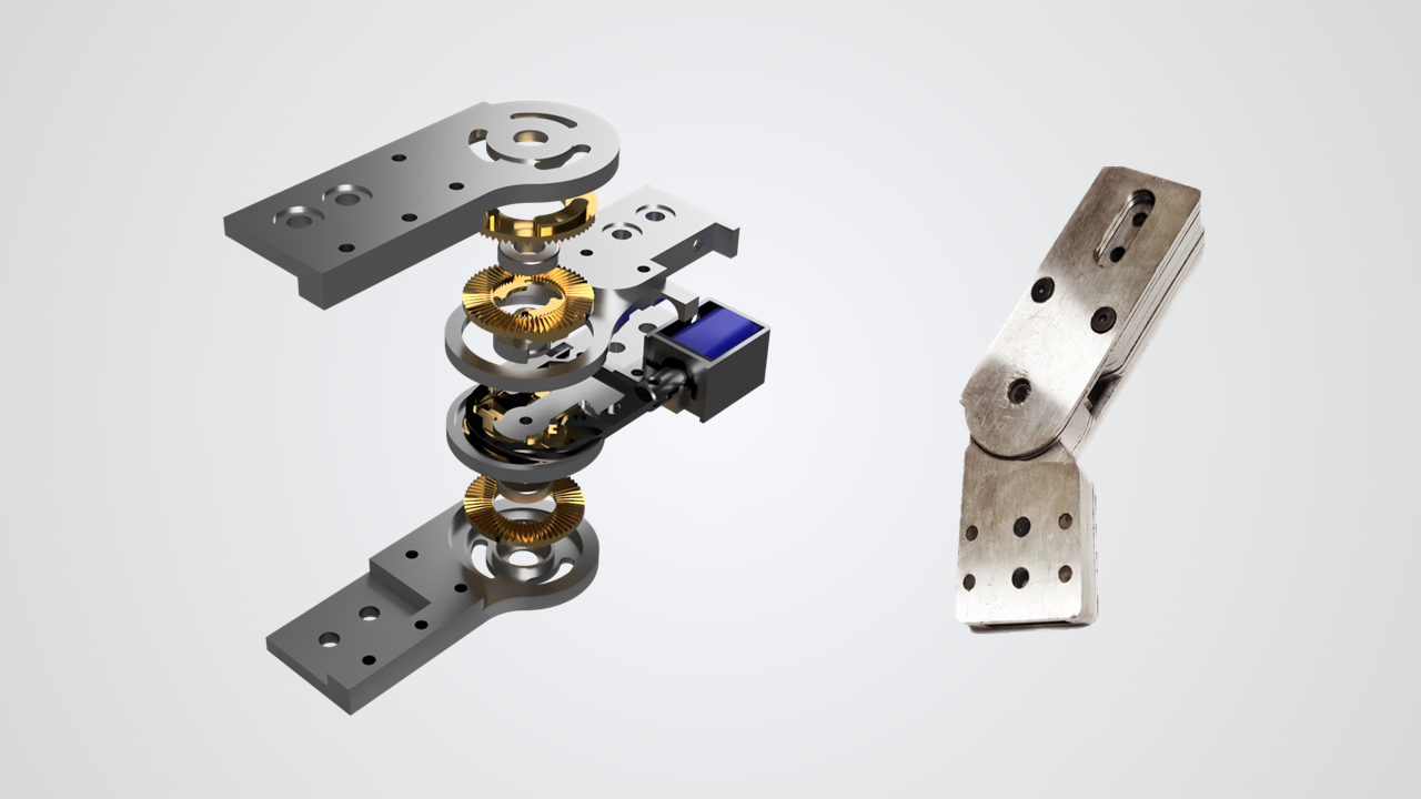
Manufacturing
The knee joint assembly, as shown in figure above was manufactured to validate the mechanism. The approach taken for manufacturing was to build the first prototype with easy-to-machine materials like aluminum. Majority of the parts were machined from aluminum using CNC machine followed by manual finishing by the technical staff. The slider in between was manufactured by laser cutting since it was small and contained sharp corners. Manufacturing inaccuracies have led to several problems in the assembly and has consumed more time than expected. First attempt to machine the clutch plates failed due to improper mounting and very thin design. The clutch plates are currently being manufactured.

Future Work
Although the above model would be functionally validated, it is extremely important to check the feasibility of manufacturing such components. The current prototype has proved to be quite unfavorable with manufacturing due the presence of complex geometrical features within a small thickness. A major redesign is being carried out to make the manufacturing phase smoother. This issue would be addresses immediately to be able to fit on the orthosis and carry out testing.

Compaction of the electronics is one of the major tasks that has to be accomplished. A careful finalization of the components has to be done and PCBs would be fabricated for the same. As far as the electronics are concerned, an extensive testing must be performed to be able to distribute it to the users with reliable functionality. This includes aspects such as optimization of battery life and inclusion of emergency features in case the joint malfunctions. Majority of the above-mentioned tasks relating to electronics are tentatively scheduled to be finished in the winter term.
Getting this project out into the market is a great challenge and cannot be achieved without rigorous testing of the mechanism for flaws. The planned progression includes testing it on able-bodied subjects in the initial phase to verify its functionality and then conduct clinical trials on actual patients. This is precisely where we might find the literature survey to be extremely useful - to understand the training procedure adopted by different research groups. This is expected to be one of the major deliverables set for the coming semester.
2018
After some critical observations made on the above-mentioned prototype, there has been an entire redesign of the knee joint. Now it’s a purely mechanical system which boasts of being affordable and easy to manufacture and assemble. The entire construction is fastener-free, except for the uprights attachment points.
New Design
Below are some renders of the new prototype


This mechanism leverages the slightest displacement caused by loading the orthoses frame with the human weight - to lock the joint. We’ll refer to the above version as v1 of passive knee joint for further reference.
UPDATE MARCH 2018
Learning from the above experience, the design has been iterated to be simpler and more robust than it’s predecessor. You can find the description below.
Design Details
This design attempts to address the failure points of the above proposed mechanisms. This revision manages to bring the same features without compromising on the locking strength. This iteration retains the design philosophy of the previous two, while simplifying the mechanism by a huge margin. This also resolves the issue of excessive friction encountered in the above version when the upright fasteners were tightened. Small features like filleted corners and hyperextension block were a result of suggestions made on the initial design.

All the involved components were laser-cut with remarkable accuracy except for the bearings and shafts involved. This design involves only 21 laser cut components in contrast to first version, which contained 33 parts. Unlike the previous joint, this is not fully-fastener free because of the screws coupling plates with the spacer. This inherits all the other features that belonged to first version of passive joint.

For the locking, it utilizes the human weight which causes a vertical displacement of 3mm, which directly engages the teeth, hence locking it. The load is now borne by a width of 9mm instead of 3mm in the old design. This massively increases the load bearing capacity of the joint. The spring used over here has been designed according to the loading needs.
Simulations
FEA was performed on the entire assembly by applying loading in 3 cases – Force, Moment and Combined. These three cases cover all the situations along a gait cycle and can be assumed safe if it passes through all the cases. The results suggest that the entire assembly would be safe in operation.

Manufacturing and Assembly
Manufacturing was majorly done using laser cutting and the process was accurate, inexpensive and fast. Having lesser number of parts in this iteration helped reduce the manufacturing time and consumed less footprint. The left-over sheet can be seen in the picture below.


The assembly was simple considering the experience gained in the fabrication of the first version. Suitable shafts and dowel pins were bought/manufactured for the assembly.
Two joints have been assembled for testing purposes and initial testing has been carried out by wearing it on to the author’s KAFO. The prototype will undergo testing on a Universal Testing Machine where a suitable static load will be applied on to the joint and it will be tested for its endurance.
Summing up, this design variant of the knee joint not only inherits the features from the first variant but also adds some major assembly benefits while maintaining the design philosophy. Laser-cutting has been the choice for fabrication not only because of speed and cost benefits but also because of it’s ability to machine intricate shapes.
UPDATE MAY 2018
I have finished my poster presentation on this project and this officially wraps up my B.Tech process. However, I am continuing my term here in the summer for wrapping this project up. Here’s my poster!

Also, here’s the report for my project. Hope you learnt something from this!